Pocket Amp
I started this as an affordable holiday gift and kept revising it until the amplifier had controls I would actually use with a guitar or bass.
At a glance
Project Result
Version 3 fixes the input-loading problem from the second design, adds adjustable voicing and a bright switch, and fits the complete amplifier onto a custom 1.1-inch board.
- Power
- 9 V battery
- Amplifier
- LM386 with a 50 mm speaker
- Status
- Done
README
Project Notes
Overview

The Pocket Amp is a small guitar amplifier built into an Altoids tin. It is powered by a 9V alkaline battery and uses a basic LM386 audio amplifier with a small 50 mm speaker. The goal was to create an affordable holiday gift that could also be refined into a small production or wholesale product.
Version 1
Version 1 used two LM386 amplifiers in a push-pull configuration. I expected the second device to add useful power, but a 9 V battery did not provide enough headroom to justify the added complexity.
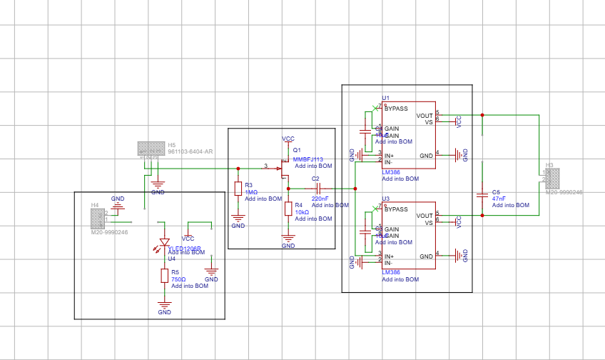
A rough schematic of the Version 1 amplifier.
The speaker was a high-end 50 mm subwoofer designed for use in headsets and other small electronics. It was a good speaker for this application. The speaker and the rest of the amplifier stayed consistent through the later versions and have not needed to be changed.
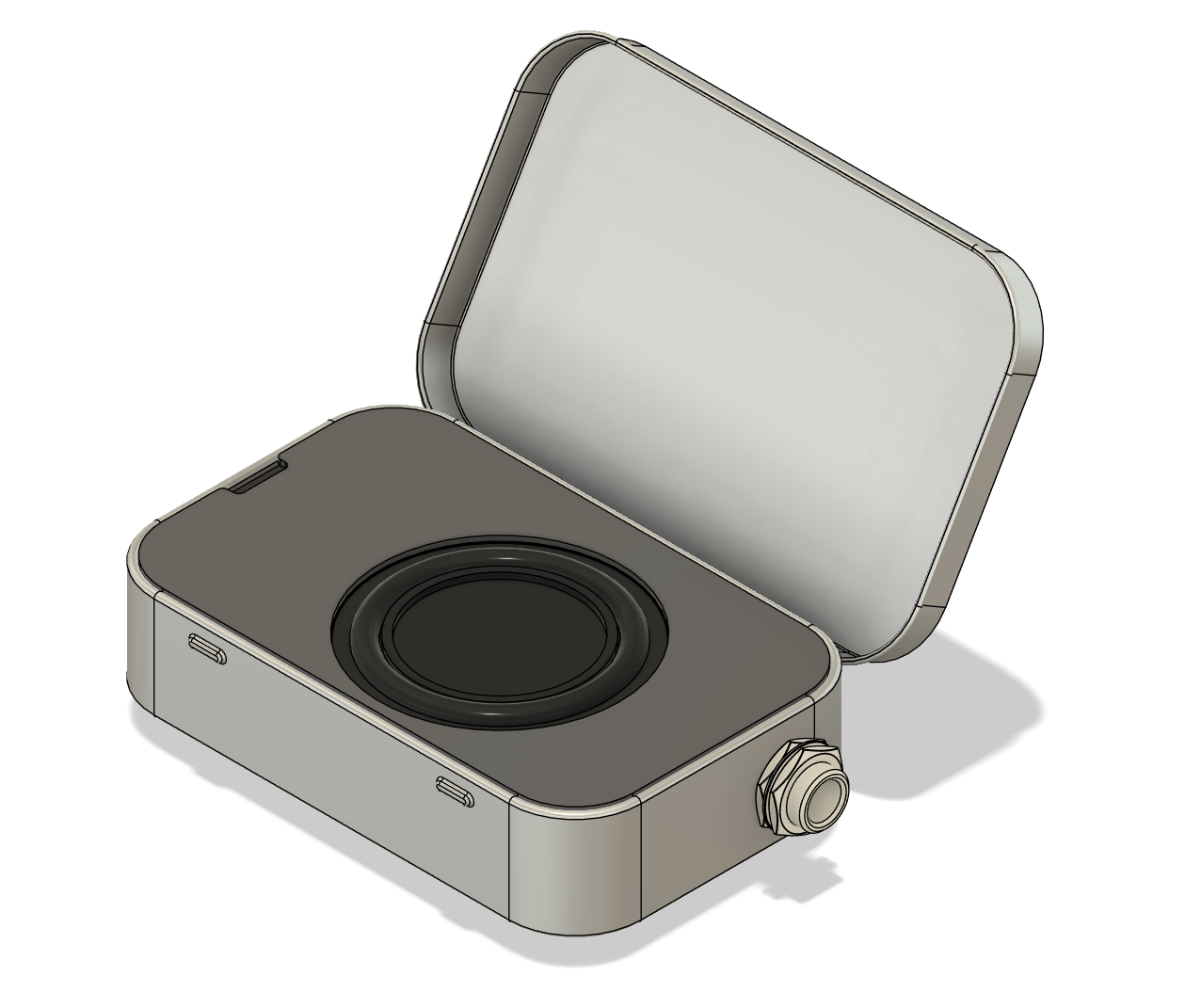
Version 2
The second version of the amplifier removed the second LM386. It seemed unnecessary for the goals of the project and caused more issues than it solved. For this version, I followed the LM386 documentation more closely. The biggest change in this version was the addition of a static equalizer.
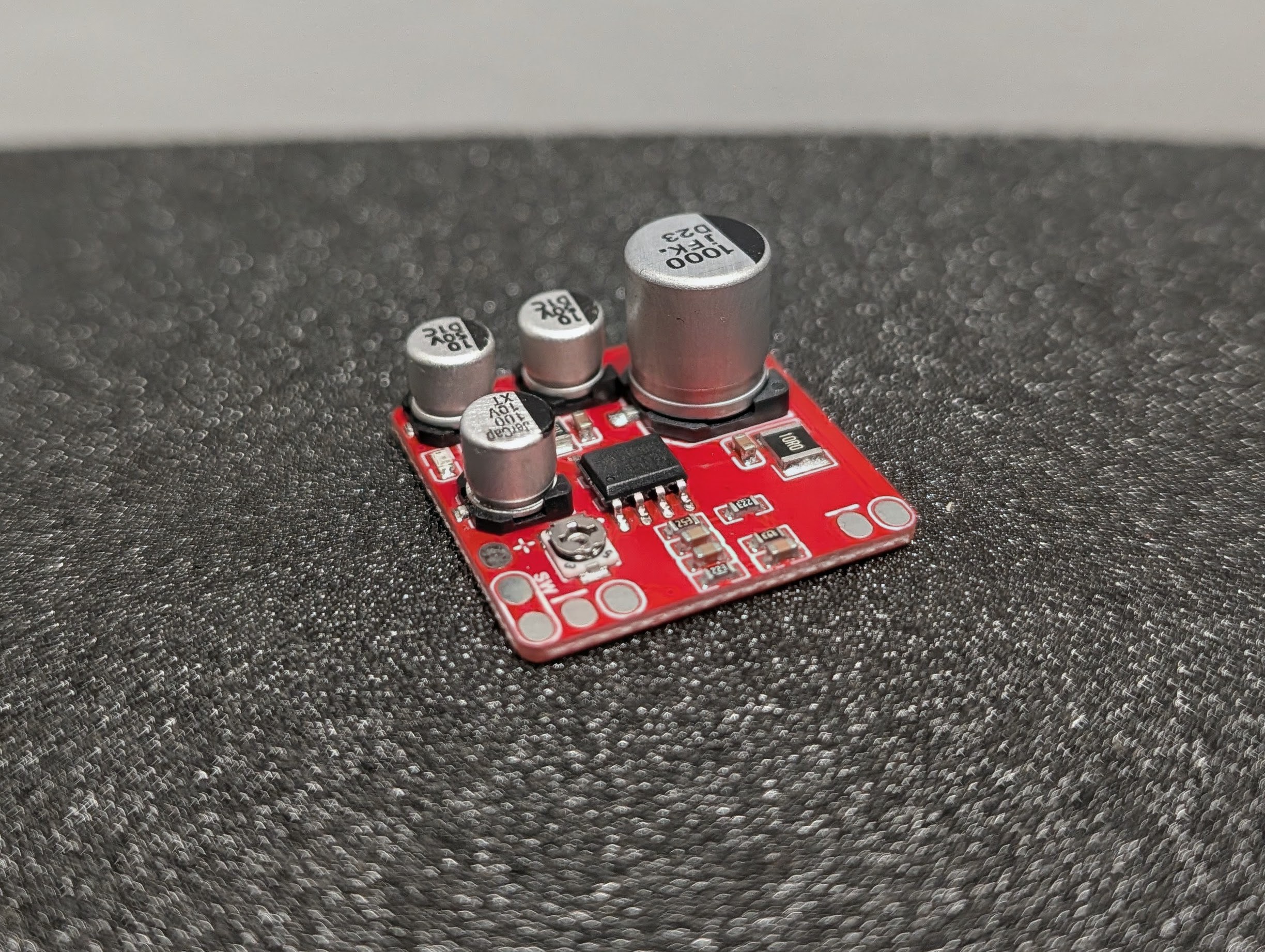
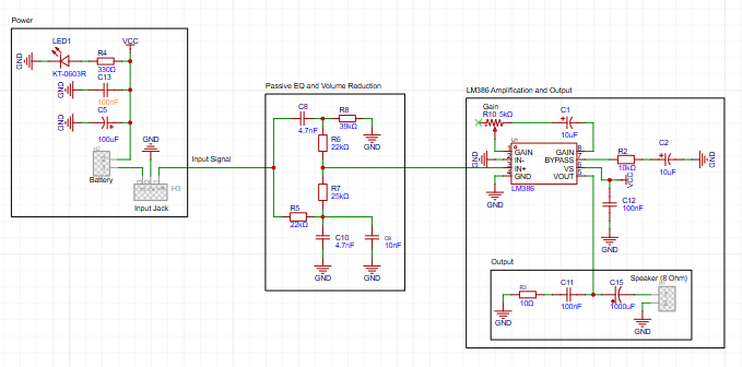
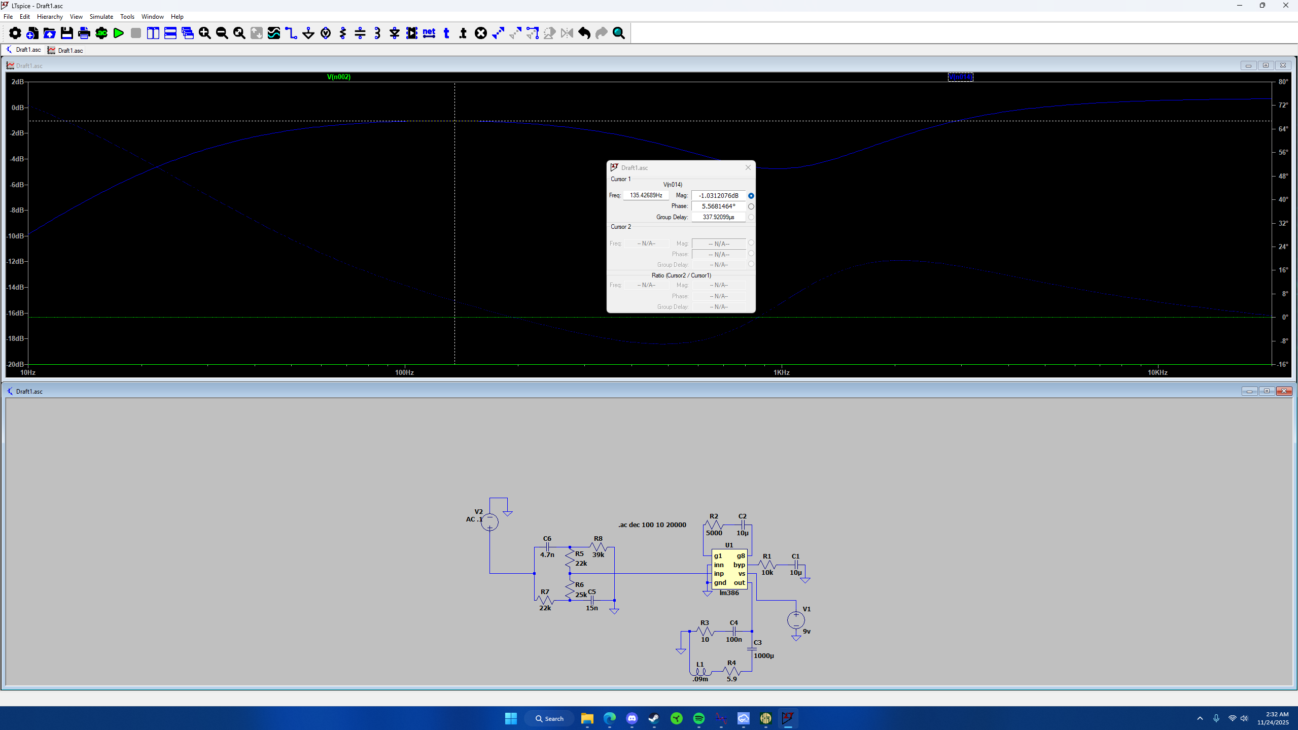
The equalizer is made from a combination of a low-pass and high-pass filter to scoop out the mids and create a more pleasing tone. Below are some frequency response charts created through a SPICE simulation.
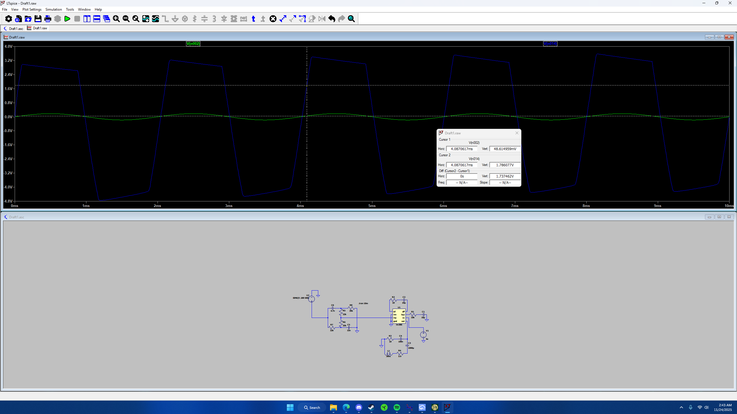
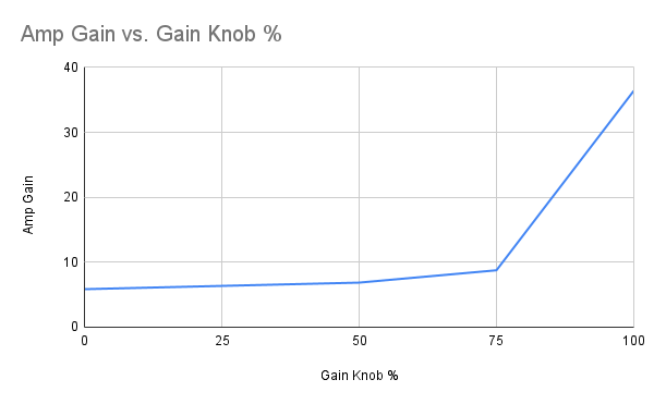
This amplifier also included gain adjustment. Using a trim pot between the two gain pins on the LM386, I was able to set the gain to the desired level. Below are some simulations showing how the potentiometer behaved.
The main flaw with this version was the removal of the buffer circuit. This made the input impedance too low, which negatively affected the guitar’s frequency response and caused poor audio quality. The third version is planned to solve these issues and add more useful features.
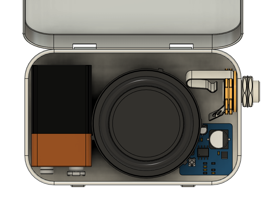
An inside view of the second version amplifier.
Here is a short audio demo of the Version 2 Pocket Amp being played.
Version 3
Version 3 fixed the input problem from Version 2 and gave me enough control over the sound to make the amplifier useful with both guitar and bass. The complete circuit still had to fit inside the same Altoids tin.
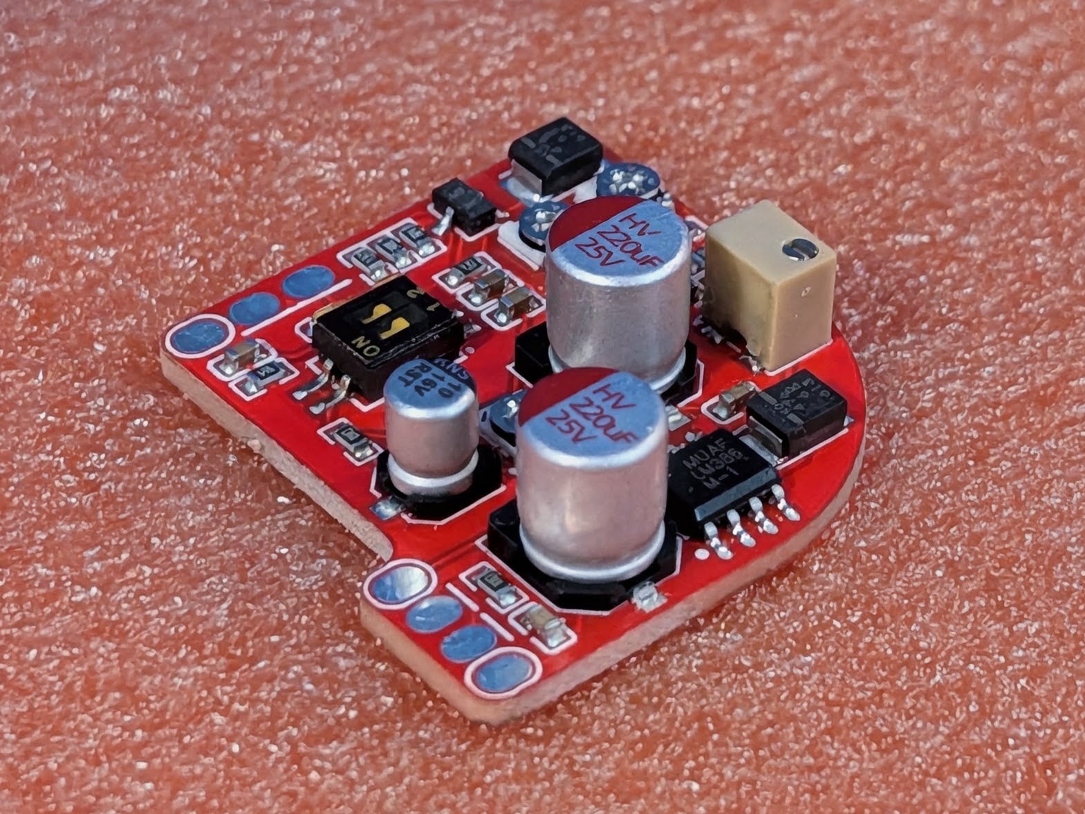
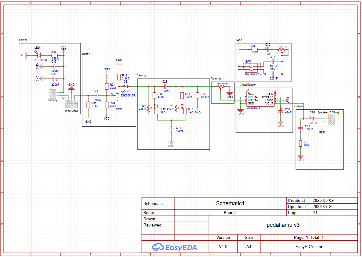
The biggest change was bringing back the input buffer that was missing from Version 2. The buffer gives the guitar a much higher input impedance, which keeps the pickups from being loaded down and losing high-frequency response. It also provides a better signal for the controls that follow it.
After the buffer, the signal passes through two adjustable voicing controls. Instead of being limited to the fixed mid-scoop used in Version 2, I can change the balance between the low, middle, and high frequencies. This gives the amplifier enough range to work with both guitar and bass.
I also separated the gain and volume adjustments. The gain control changes how hard the LM386 is driven and how much distortion it produces, while the 500 kΩ volume control sets the final listening level. The bright switch adds selectable capacitance to the LM386 gain network, which increases the upper-mid and high-frequency response when a brighter sound is needed.
Version 3 audio demos
I recorded four short examples with the finished amplifier. I used guitar and bass because the controls behave differently with each instrument, especially at brighter and more distorted settings.
Guitar melody
Blues guitar
Funky bass
Grunge bass
This is the final Version 3 schematic, from the input buffer through the voicing, volume, gain, and bright controls to the LM386 output stage.
Control simulations
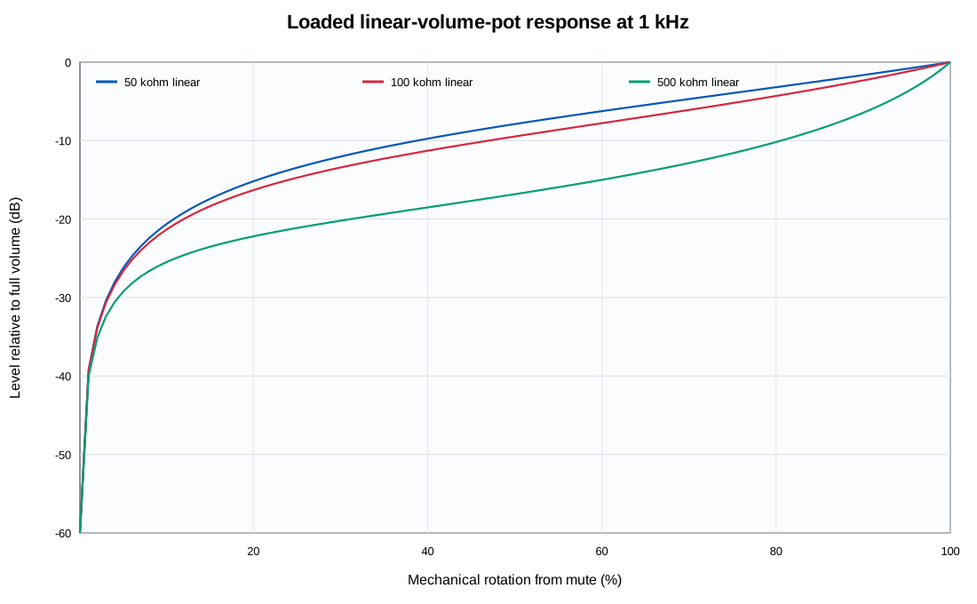
I compared 50 kΩ, 100 kΩ, and 500 kΩ linear volume controls with the load of the following stage included. The 500 kΩ option produced the most useful adjustment curve at 1 kHz.
With that value selected, I swept nine combinations of the two voicing controls. The range covers a relatively flat response, several mid-scooped settings, and stronger low-frequency emphasis.
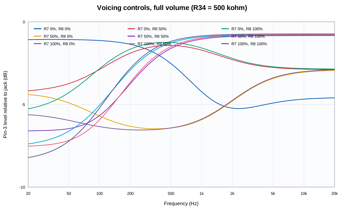
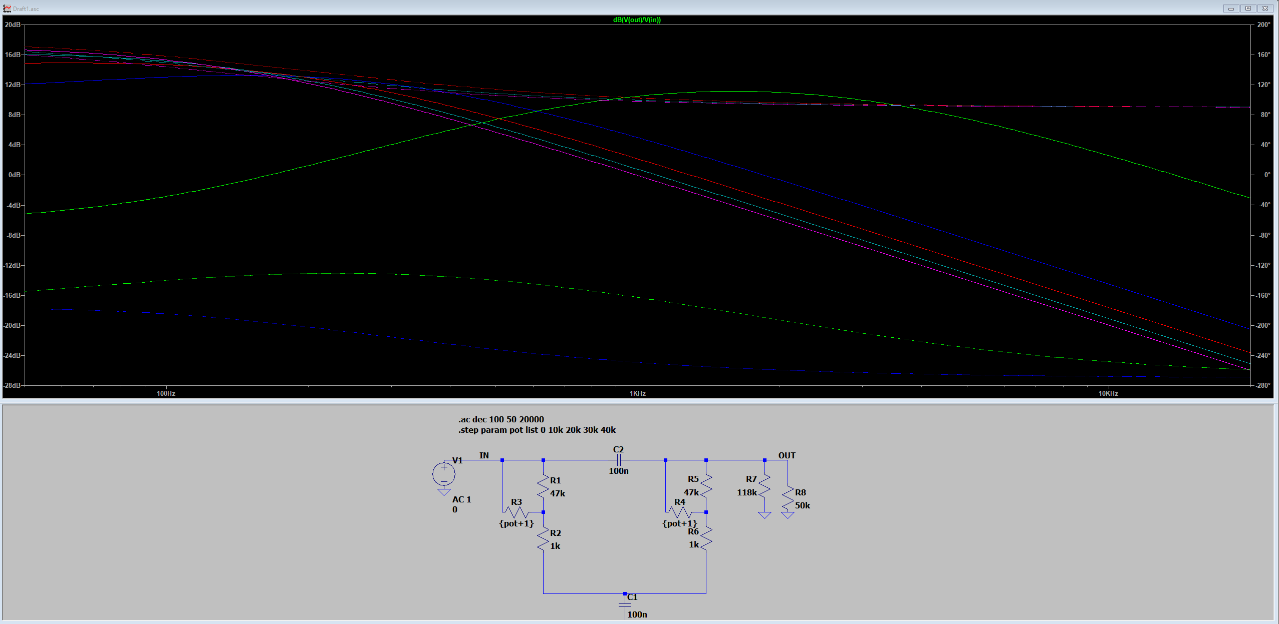
The original LTspice sweep below was the first check of how the voicing network moved the frequency response.
Bright-switch simulations
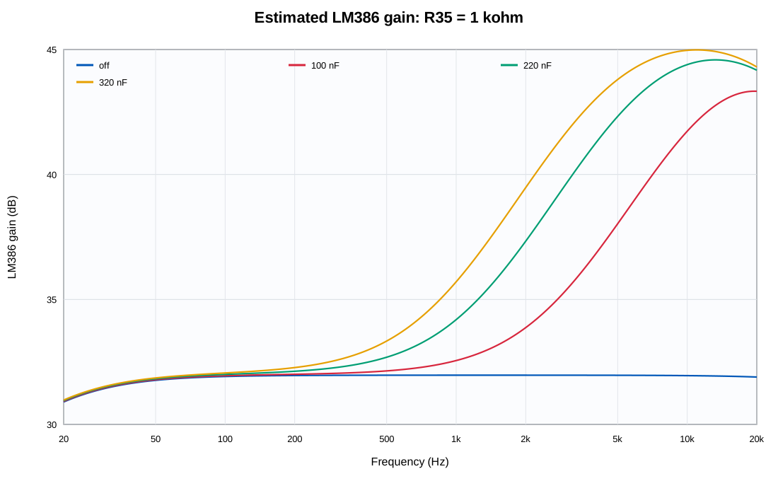
I tested the LM386 gain and bright network at both ends of the 1 kΩ R35 range. Each plot compares the switch off, 100 nF, 220 nF, and both capacitors together at 320 nF. With R35 at 1 kΩ, each step adds progressively more upper-mid and high-frequency gain.
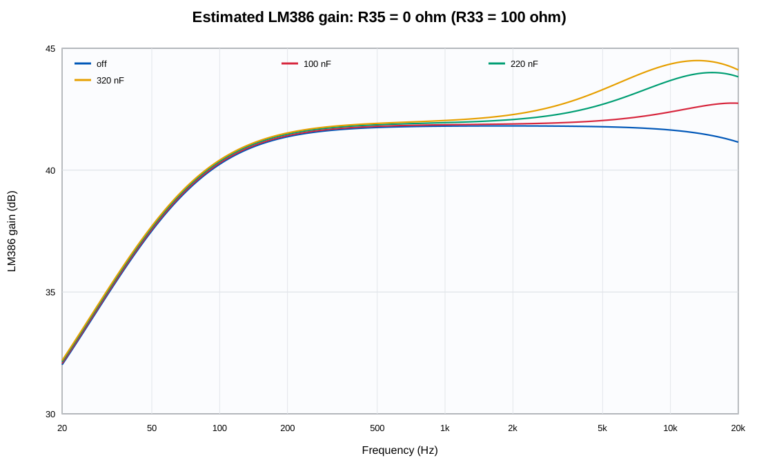
At 0 Ω, the LM386 is closer to maximum gain. The capacitors still shape the upper response, but the full curve moves higher.
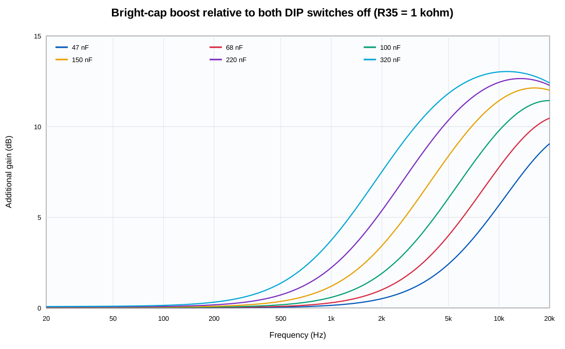
Sweeping 47 nF through 320 nF made the tradeoff clear enough to choose two useful steps rather than add another continuously variable control.
The final comparison includes the buffer, midpoint voicing settings, full volume, LM386 model, output coupling network, and a modeled 6 Ω speaker load. It is the closest small-signal representation of the complete circuit.
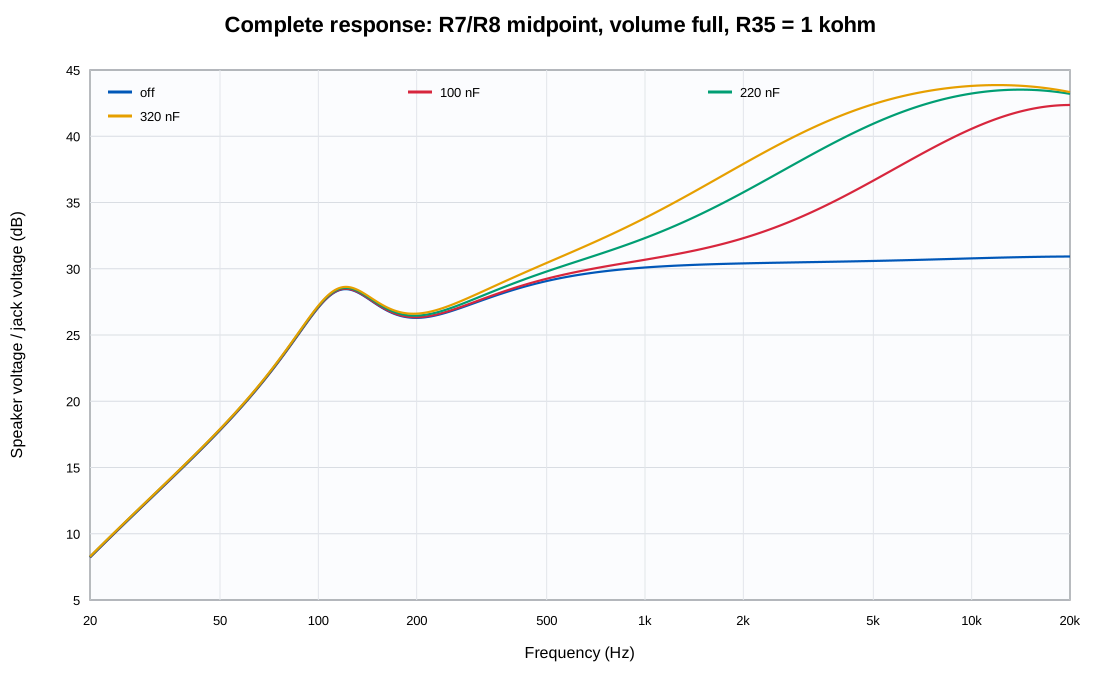
These are small-signal AC simulations, so I used them to compare component choices—not to predict clipping, battery sag, enclosure acoustics, or high-gain stability.
PCB layout
The two-layer PCB fits the complete circuit into an envelope of roughly 1.1 by 1.1 inches. Its curved edge follows the space available beside the speaker, and the input section stays separated from the noisier LM386 output path as much as the enclosure allows.
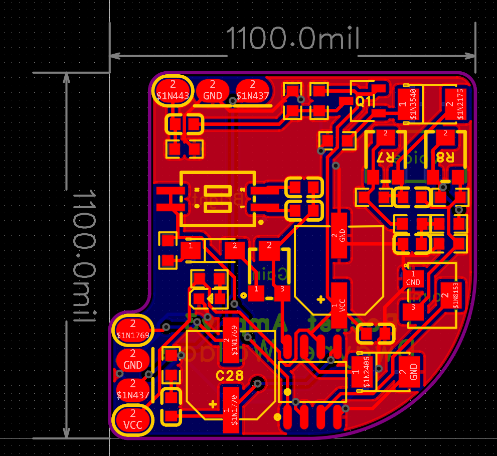
The board worked after assembly, and I made the four recordings above with the finished amplifier. The input buffer solved the main problem from Version 2. I still want more time with the amplifier before calling every control value final, but the current voicing, gain, volume, and bright settings cover the range I was trying to reach.