Vertical Profiler 2026
I led this profiler from the first requirement list through two finished prototypes, pool testing, and the 2026 competition.
At a glance
Project Result
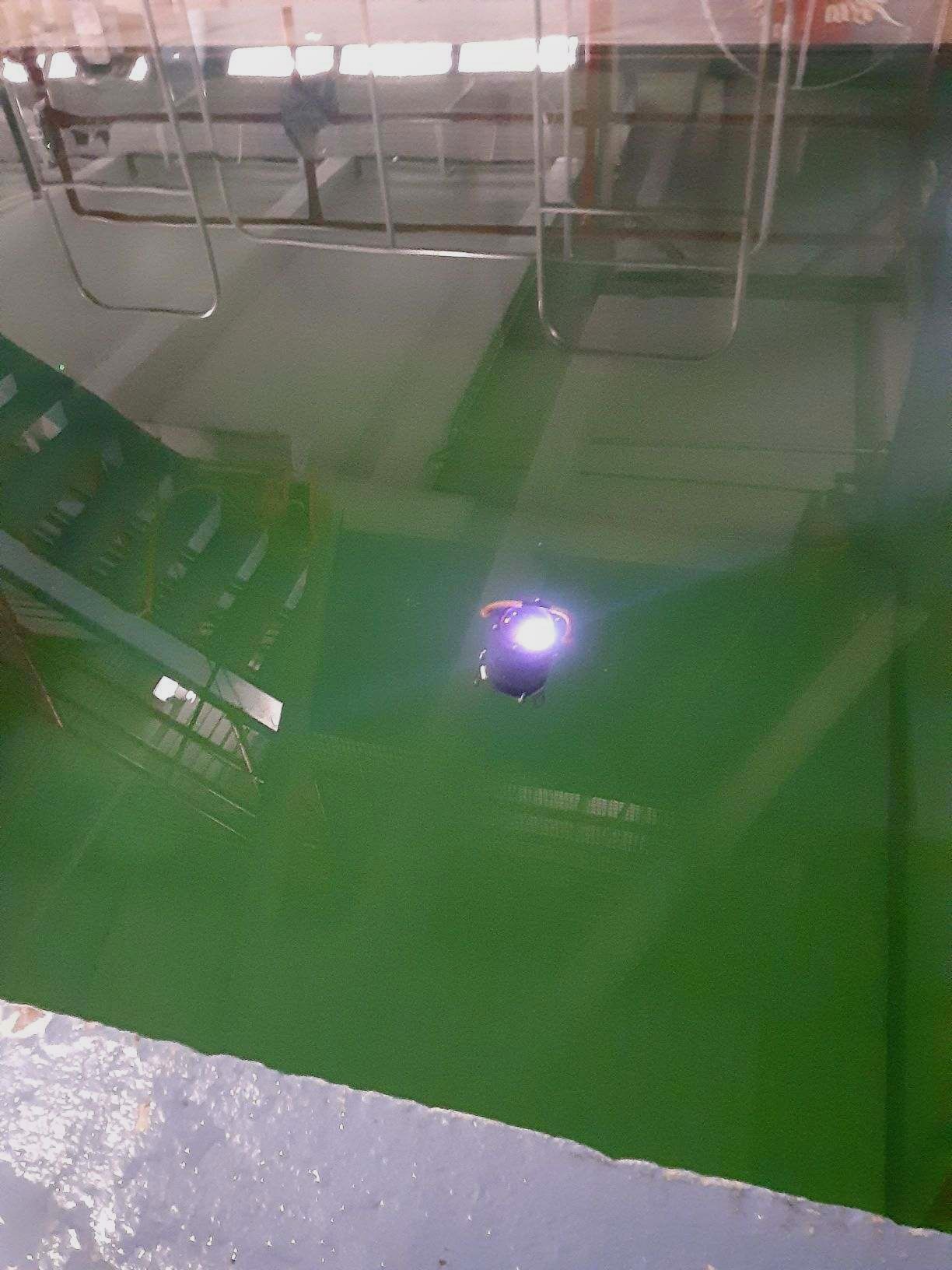
We completed two profilers on schedule and within budget. After a final ballast adjustment, the system completed the product demonstration without a major problem and earned all 85 points available for the task.
- Rating
- 5 m depth and −30 °C
- Material cost
- Less than $200 per profiler
- Competition
- 85 of 85 points
README
Project Writeup
Overview
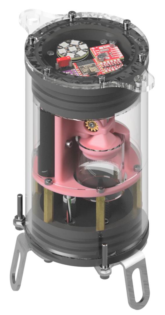
I led this project for the 2026 MATE ROV International Competition in Newfoundland and Labrador. The profiler had to run in an ice tank rated to −25 °C, so cold-temperature sealing and material behavior affected the design from the beginning.
We finished two profilers rated for 5 m depth and −30 °C operation. Each one cost less than USD 200 in material.
This was the largest project I had led from the first requirements through competition. I enjoyed the technical work, but I found that I was most interested in keeping the mechanical, electrical, software, budget, and schedule decisions connected.
Goals and Requirements
I built the first requirement list from the MATE ROV safety rules, the competition environment, our own product goals, and a total project budget of USD 500.
The profiler needed to:
- Operate at a depth of at least 3 m
- Operate down to −25 °C
- Resist glycol-based antifreeze
- Use a transparent housing
- Have a professional appearance
- Meet the MATE ROV battery, power, and pressure-relief rules
- Complete the scored vertical-profiling mission
- Stay within the USD 500 project budget
We later rated the finished design to 5 m and −30 °C after completing the supporting calculations and tests.
Planning the Project
One of my main goals was to keep requirements separate from solutions. The task told us what the profiler needed to accomplish, but it did not require a syringe, servo, enclosure material, or control method. I wanted those choices to stay open until we had compared them.
I turned the requirement list into a Work Breakdown Structure, assigned subsystem owners, and created the first schedule and cost allocation. A subsystem was not fully planned until someone owned its technical result, deadline, and part of the budget.
We also used an Interface Control Document to agree on the connections between the mechanical, electrical, and software work. Mounting geometry, connectors, voltage levels, and message formats are not exciting design work, but defining them early let people work independently without creating as many problems during integration.
For major decisions, I asked for a trade study, calculation, or test that explained why an option fit this project. That process mattered when our first buoyancy-engine choice failed. We had moved too quickly on the actuator, and the prototype did not produce the displacement we expected. Reopening the comparison led to the simpler rack-and-pinion syringe system used in both finished profilers.
Mechanical Design
The enclosure is machined from transparent PVC. We selected it after comparing its low-temperature behavior and resistance to the glycol-based antifreeze used in the ice tank.
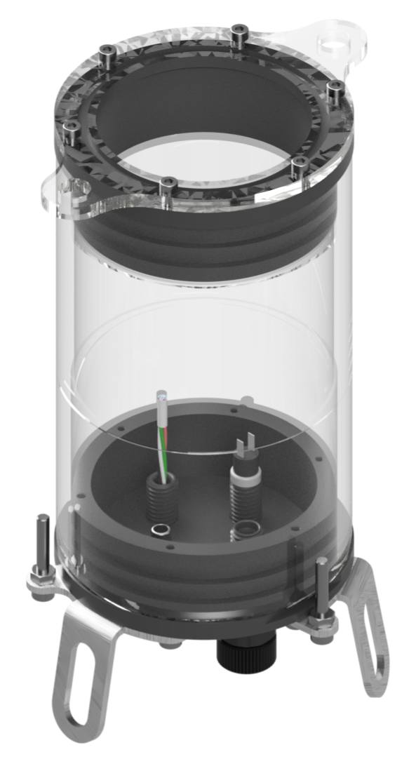
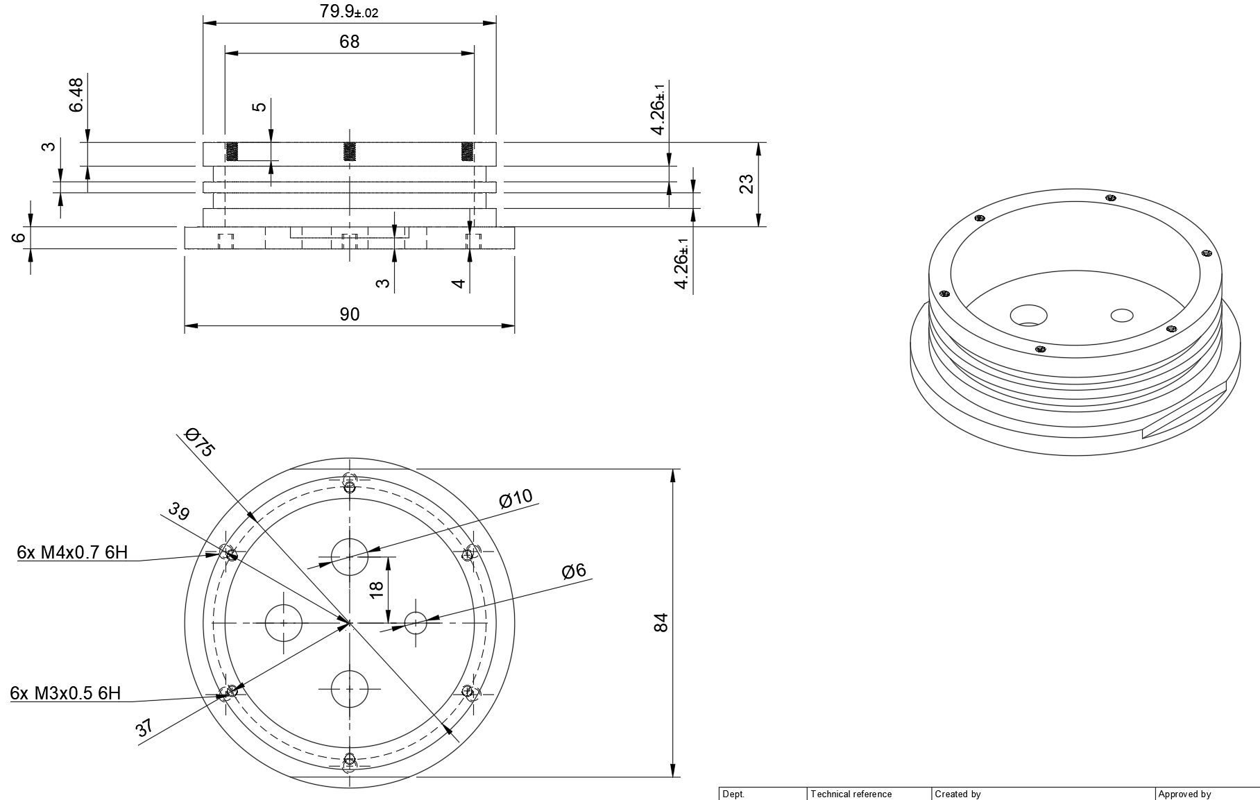
The seal was one of the parts I did not want to judge by room-temperature fit alone. We calculated the PVC contraction and checked O-ring shrinkage and squeeze at room temperature and at the −30 °C design condition. Using PVC for the main enclosure parts also reduced the mismatch between materials as the temperature changed.
A team machinist made two prototypes from the released drawings. Working through tool access, tolerances, and machining order with the person making the parts improved both the design and the drawings.
Buoyancy Engine
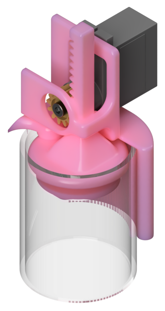
The finished buoyancy engine uses a 100 mL syringe driven by a 9 g servo and a rack-and-pinion mechanism. It exceeded the required displacement, supported the 5 m pressure rating, and drew about 500 mA at stall.
Electronics
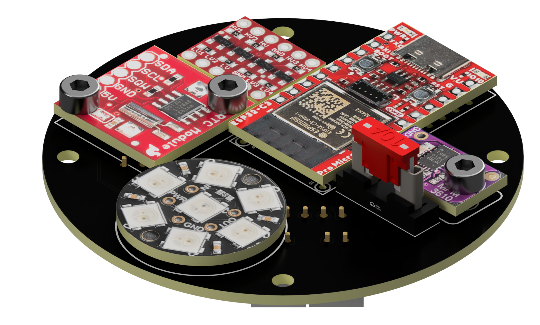
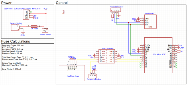
A circular PCB at the top of the internal structure combines the power, control, timing, and status hardware. This removed much of the loose wiring that made the 2024 profiler difficult to assemble and service.
We chose the ESP32-C3 because the SparkFun Pro Micro-style board fit the available PCB area and provided the processing and Wi-Fi support we needed without a separate radio module.
The profiler does not use an external antenna, which made RF transparency another enclosure requirement. The 65 mm PCB also holds the level shifter, real-time clock, LED array, and buck converter.
Software and Controls
The ESP32-C3 creates its own Wi-Fi network. A phone or computer can connect directly to the profiler, so there is no separate base station to set up.
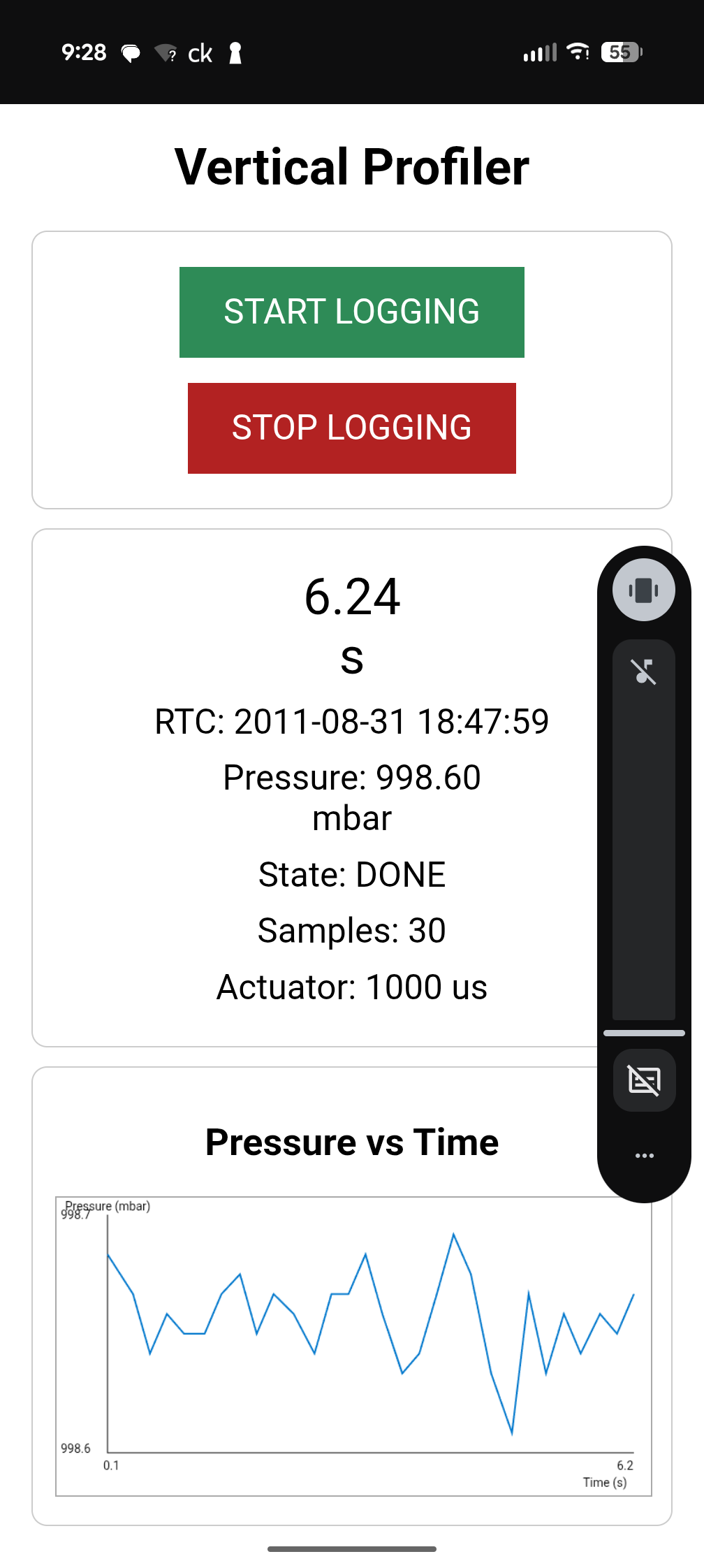
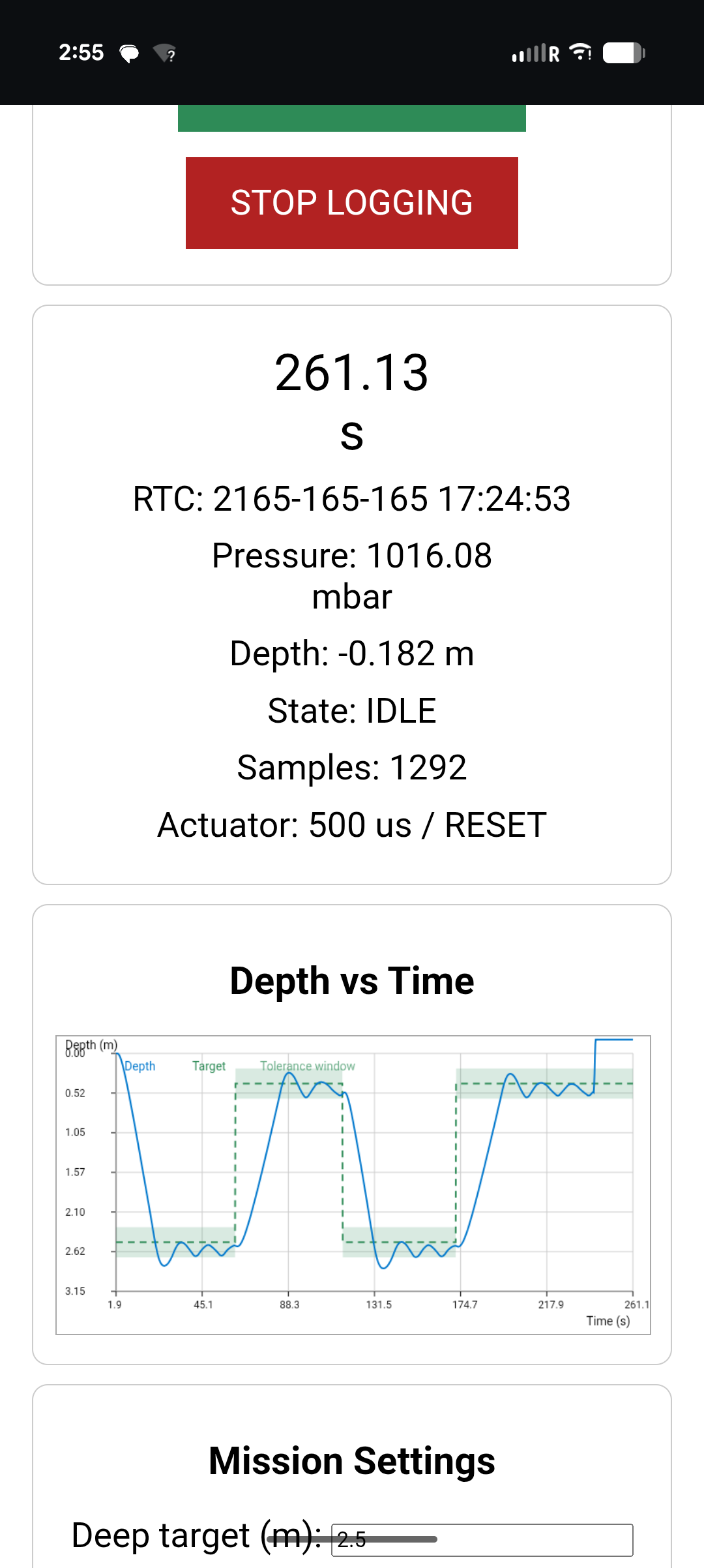
The web interface starts and stops a profile, displays telemetry and the required depth graph, and exposes the PID, mission, and manual controls. We can change the mission settings and controller gains without reflashing the ESP32 or opening the pressure enclosure. That made each pool test much faster and reduced the number of times we disturbed the seal.
View the Vertical Profiler 2026 GitHub repository
Problems and Revisions
The first major failure was the buoyancy engine. Our original Actuonix actuator bound under load and did not reach its predicted displacement. Because we had selected it before finishing a complete trade study, there was not a strong reason to keep trying to tune around it.
The completed comparison led to the rack-and-pinion syringe design used in the final profilers.
Depth control was the second major problem. A ballast error of only 0.2 g could move the neutral point enough for the profiler to oscillate around the wrong depth. Pool testing alone made it difficult to separate a controller problem from a ballast or setup problem, so I built the simulator to compare the control methods under repeatable conditions.
View the Vertical Profiler Simulator page
Final Result
We completed two competition-ready prototypes on schedule and within budget.
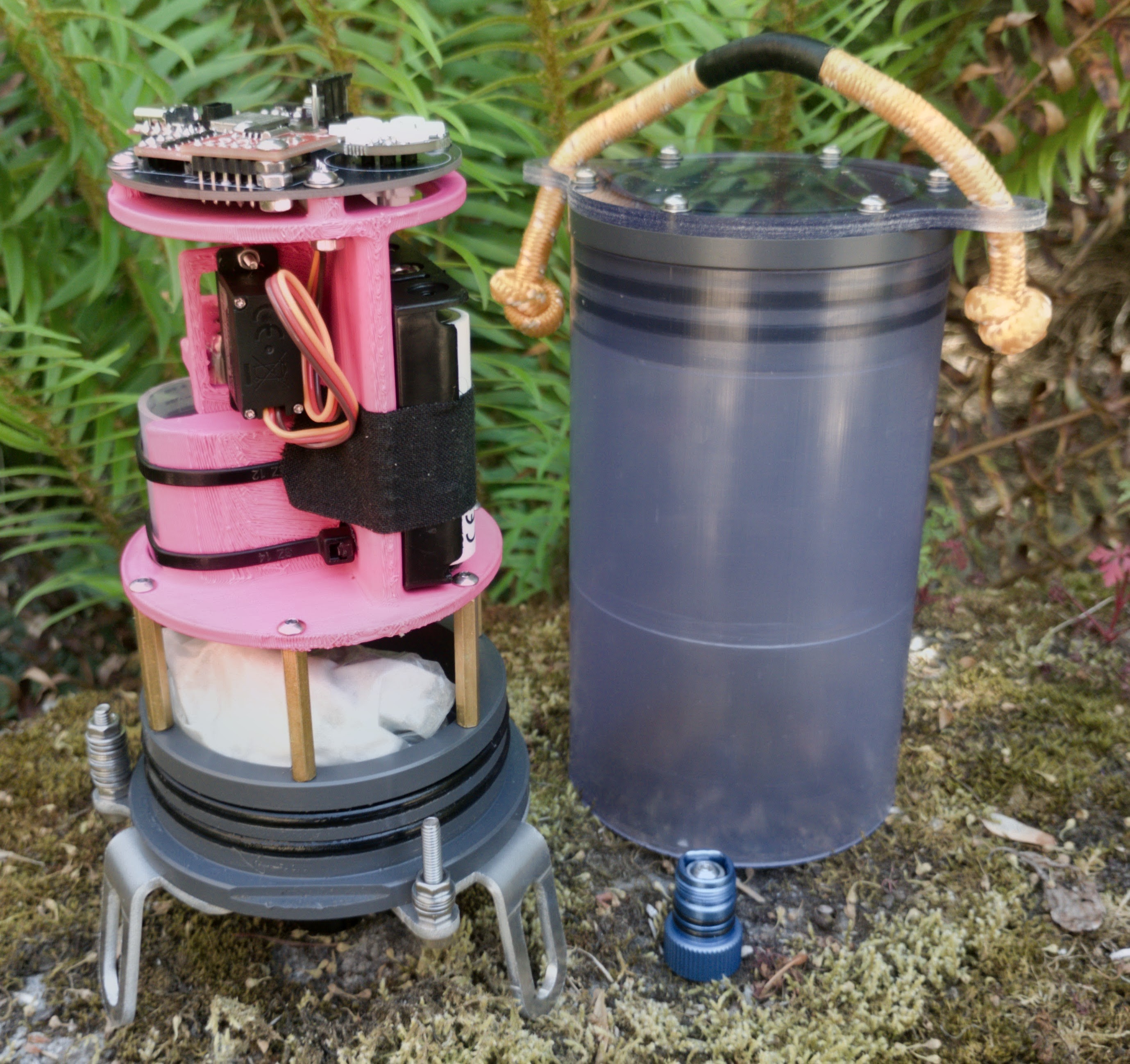
At competition, we set the final ballast and completed the product demonstration without a major problem. The profiler earned all 85 points available for the task.
The most important result for me was seeing the design process recover from a poor early choice. The first actuator failed, but the requirements and comparison work gave us a clear way to replace it without losing the rest of the project.
Supporting Documents
The full project folder contains the remaining CAD files, calculations, PCB documents, reports, and planning records.